Tie-FenLock 300 Depot Control System
| Company | Fenix Rail Systems |
|---|
Images

Fenix recommend the Tie-FenLock 300 DCS for large, complex depots where a single point of control is required and where a full signalling system is too thorough.
General Operational Overview
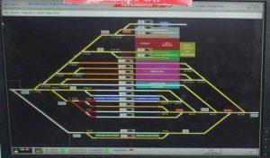
The Tie-FenLock 300 system is presented to the operator in one or both of two ways. The first option is by using a Visual Display Unit (VDU), as shown in figure 1. Any equipment controllable by the user can be clicked with the mouse using the left-click for standard operation, and a right-click for failure/administrator roles.
As an additional feature, the software can be configured to show a car count, which is achieved by taking the axle count and dividing by the number of axles per car/carriage/coach This becomes of benefit when permissive working is specified as it allows the operator to see the remaining stabling capacity.
Each interlocking request also features a yes/no option to complete the operation. This is to prevent accidental requests. Fault messages and degraded mode operations provide an additional pop-up image and window and each must be acknowledged before the system executes a new request.
The most commonly used function on a Tie-FenLock 300 system is setting a route which is performed by 5 mouse clicks:
| Start |
– |
– |
– |
Finish |
|
Click on the signal at the start of the desired route,
|
Select “START” from the drop-down list that appears,
|
Click on the signal at the end of the desired route,
|
Select “DEST” from the dropdown list that appears,
A message appears “Set route A to B?” with buttons YES and NO. The YES/NO are blanked out for 3 seconds before becoming available to mitigate erroneous setting. |
Click YES
If the route conditions are satisfactory, the route sets and a message “Route A to B set” appears and the VDU reflects lineside equipment states. If the route conditions are not satisfactory (e.g. points locked in the incorrect lie), the route does not set and a message “Route A to B setting cancelled – Points C locked reverse”. |
—
RSP Operation
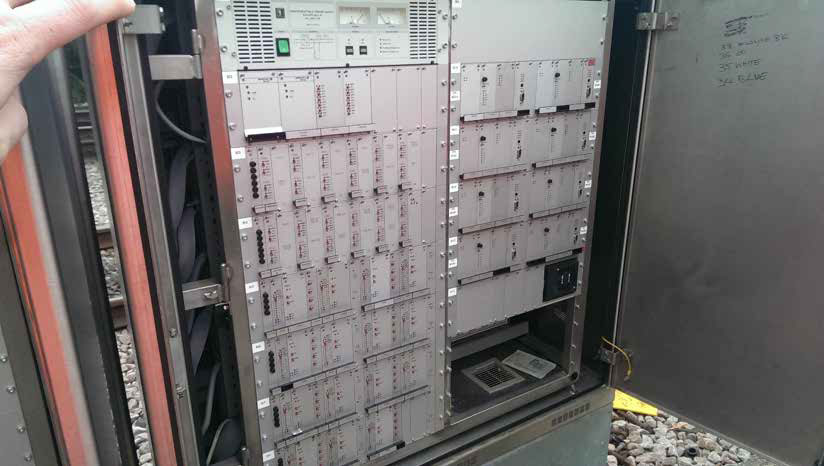
The RSP is presented as push buttons mounted on a steel panel, rather than on a screen. However, the process for setting a route is not dissimilar.
| Start |
– |
Finish |
|
The operator inserts and turns a key to power up the RSP, checking that the “running” lamp is lit correctly
|
The operator then presses the button for the route that they wish to set;
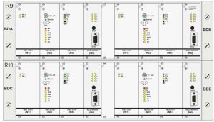
The “route” white LED begins to flash as the route begins to set, The “route” white LED becomes steady when the route is set successfully, The “lock” red LED shows when route setting is not possible. |
To cancel the route, the operator presses the “delete” button and the appropriate “route” button simultaneously.
To cancel the route, the operator presses the “delete” button and the appropriate “route” button simultaneously. |
Other Products From Fenix Rail Systems
Tie-FenLock 400 Depot Control System


Tie-FenLock 200 Depot Control System
Tie-FenLock 100 Depot Control System